Future Commit: Lego Building Robot Arm (Part 1)
Snapwhiz914 / October 2024 (608 Words, 4 Minutes)
Background
This story behind this complex, almost unrealistic-sounding project has a simple backstory. After spring finals in 2023, I got a very well-targeted ad for a robotic arm on amazon. I decided “why not, something to have fun with over the summer” and bought it. Around the same time I finally got around to building a lego set my family got me for Christmas, and seeing the two together on my desk gave me an idea. I’ve seen videos of robotic arm stacking items ⸺ what if that item was a lego?
Process
Initial thoughts
Obviously this idea can only go so far. Fully automated lego building has quite a few requirements:
- The positions of the next lego to be put down and its target are known. I didn’t trust that the servos were accurate down to the centimeter with their set positions, so I looked into using vision to detect the positions.
- The gripper dexterity is equal to or more than that of a human hand. Some lego pieces are unwieldy to put down. The gripper that came with the arm is sufficient for simple lego pieces, and the arm isn’t large enough for a hand-like gripper to be practical.
The goal of this project is the ability for the arm to pick up, place and push down a lego piece on another. Ideally I would be able to translate existing lego designs from software like BrickLink Studio into gcode-like instructions, but that’s a later goal.
Requirement #1: Electrical and Mechanical
Initial testing of the arm made it obvious that I couldn’t rely on the arm to have enough accuracy with its setpoints. The first arm joint wasn’t powerful enough to support the rest of the arm, so it would fall over after about 10 seconds of the motor stalling.
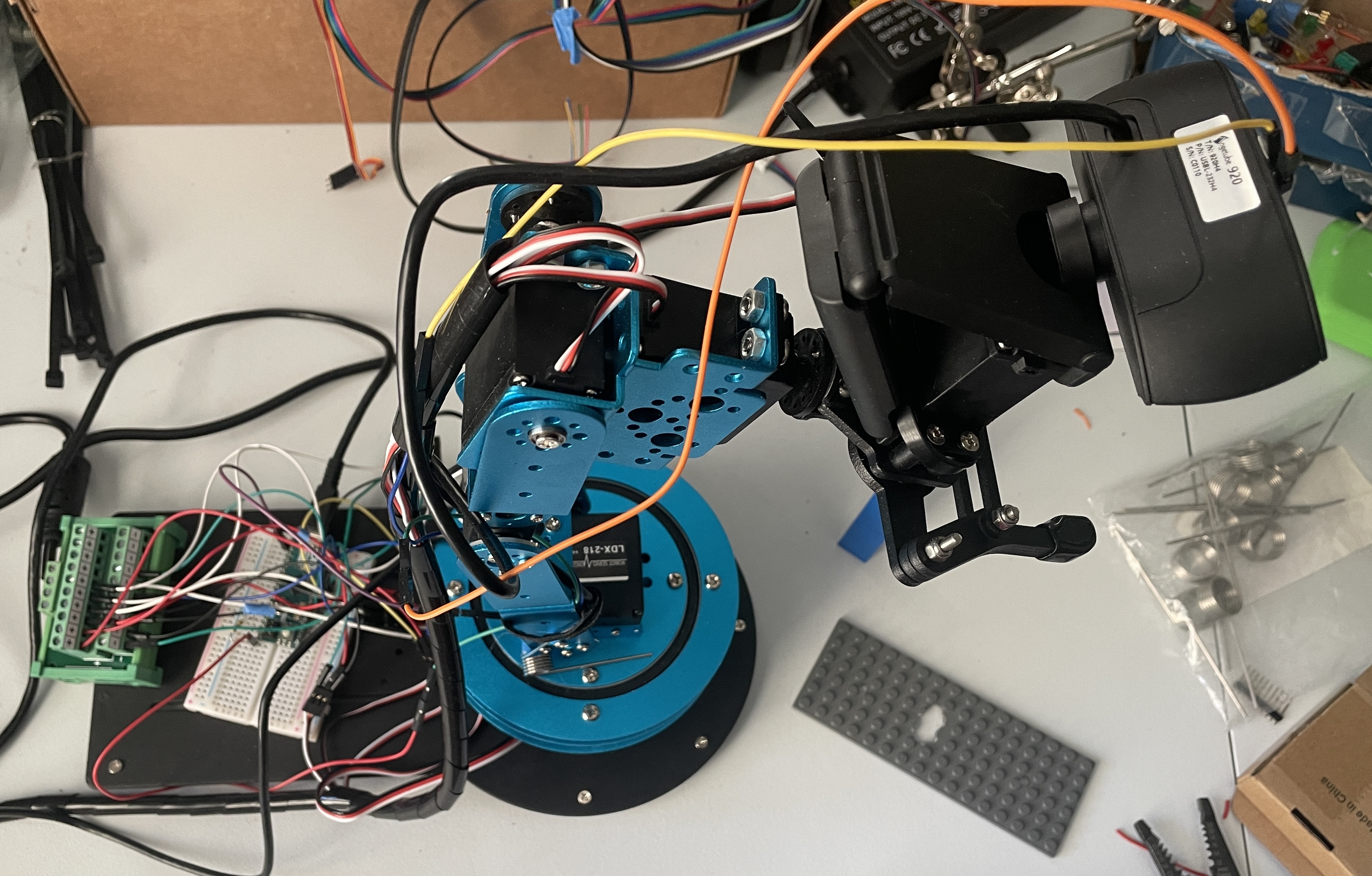
I knew that I would have to make the arm reasonably accurate (and powerful enough to at least hold itself up) before using vision, so I tackled that first. According to the servo website, they draw up to 3A of current when stalling. The out-of-the-box power adapter only supplied 3A, so I got an adjustable power supply that allowed up to 12A of current draw. I replaced the microcontroller that came with it with an arduino micro, and connected the servos to it via jumper pins and powered them with a terminal block connected directly to the supply.
In addition to an electronic renovation, I added some torsion springs to the first arm joint to assist the servo when it has to support the entire weight of the arm.

A side view of the arm. Notice the torsion springs at the “shoulder” joint and the green terminal block in the back
Requirement #2: Software and Vision
I use pyfirmata to control the arduino (and the servos) from my laptop and ikpy to do inverse kinematics to get the servo set angles for a specific position. I made a simple smoothing algorithm that moves the setpoint along a curve so the arm movements aren’t clunky.
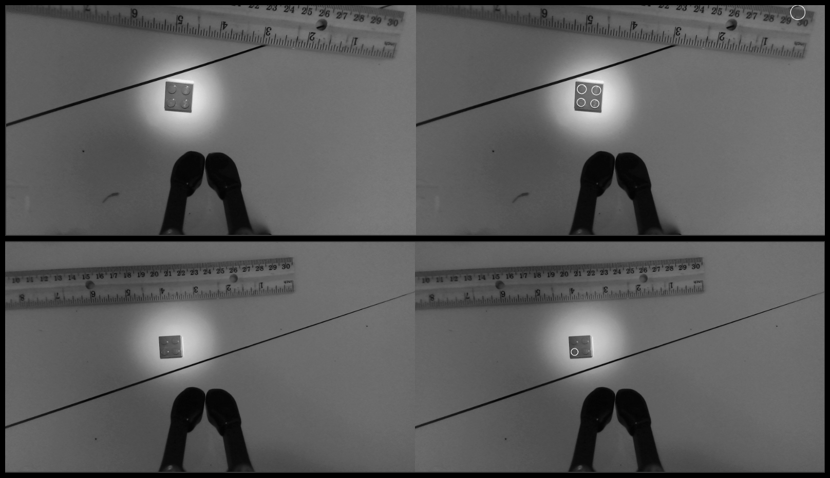
The visions is going to be the most difficult part of this project. I’ve been trying to use a Hough Circle detector to group together detected studs on bricks, however it’s not very reliable and is very prone to lighting differences. I created a makeshift cross validation program to test detectors with different parameters, but it was still too finicky. I’m looking into object detection with a neural network, which would be more reliable but would be very computationally expensive and probably use dedicated hardware (ie. a coral TPU).

Hough Circle detection algorithm run on 2 examples frame from the arm’s webcam. On the left is the raw image and the right has white circles where it detects circles. Notice the false positive on the ruler and the false negatives on three of the studs in the bottom image
Looking forward
- I will try object detection to detect bricks
- The arm movement smoothing is still somewhat choppy and jerks the entire arm when it moves causing it to change position and blur the camera, so that needs to be smoothed out.
- The camera’s focus is manual. I’m probably going to use a camera with motorized focus that I can actually control because I know approximately how far away the target brick is from the camera, so I can adjust the focus according to that distance.
Part 2 might be a long ways away since I’m at the height of fall semester business. I plan to dig in to this project over winter break.